
MIRTEC ART: The AOI Skills You Need When Solder Joints Reflect Everything
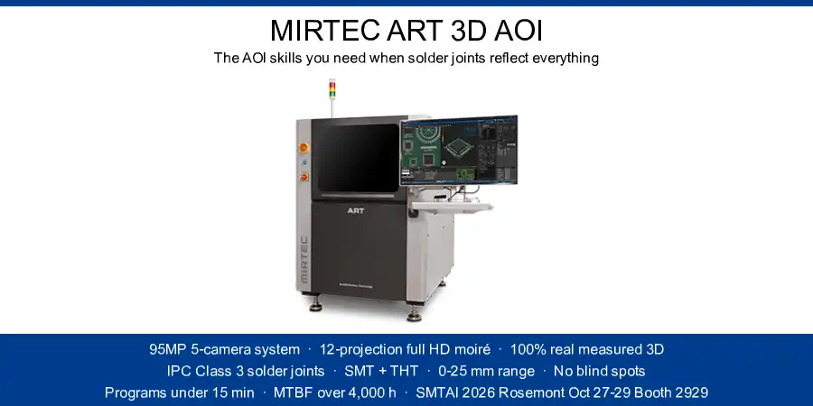
Why this matters now. At SMTA International 2026 (October 27-29, Donald E. Stephens Convention Center, Rosemont, Illinois, Booth #2929), MIRTEC will put its flagship ART 3D AOI system on the floor alongside the MV-6 OMNI and the MS-11 SPI. ART is worth a hard look not because it is one more inspection box, but because it attacks the single thing that quietly decides whether your AOI data is real: how you measure a solder joint that behaves like a mirror.
Every AOI engineer has met the same failure. The board passes, the joints look perfect to the naked eye, and the 3D height map still shows something that does not exist. That is not a software bug. That is specular reflection doing what physics always does on a bright, curved metal surface.
Skill one: telling measured data from interpolated data
Most 3D AOI systems build a height map from structured light and then repair the holes. Where the camera saturates on a shiny fillet, or where a tall component casts a shadow, the algorithm fills the gap. The picture is complete. The data is not.
The skill is to know which voxels in your height map were actually measured and which were inferred. MIRTEC’s pitch for ART is exactly this distinction: conventional AOI “often rely on algorithms to fill in data lost due to specular reflections or blind spots caused by component structures,” while ART captures 3D data from multiple directions so that “solder joints are inspected entirely on the basis of actual measured data.” The company’s own product page frames the same point as 100% real 3D solder joint inspection – total 95 megapixels across a five-way camera system, with 3D data gathered from all around the target, “five times more than traditional 3D AOI systems.”
Practically, that is a verification habit before it is a hardware feature. When you qualify any AOI – new or used – pick a board with genuinely mirror-bright joints and ask the system to show you the raw 3D acquisition, not the finished pass/fail image. If the vendor cannot show you measured points at the solder-to-terminal junction, you are looking at a well-rendered guess.
Skill two: using angles instead of algorithms
ART is built as one top-down camera plus four angled cameras – five 15 MP CoaXPress colour heads in the launch configuration – paired with four Full HD digital projectors and 12-projection digital blue moiré. The original 2024 launch release described it as the world’s first 75 MP multi-camera / full HD 12-projection 3D AOI system; MIRTEC now specifies the platform at 95 MP across the same five-camera architecture.
The engineering logic is simple and it is the part worth internalising: when one head saturates on a bright surface, another head is already looking at the same point from a different angle and can supply the missing geometry. The angled heads also see into shadow zones that a purely top-down system cannot reach at all. The skill for the process engineer is to stop treating camera count as a marketing number and start asking the operational question – which of my defect classes live in the angles? Solder fillets on THT pins, gull-wing and J-lead terminations, QFN side wetting, and shielded joints under a tall can are all cases where the answer sits off-axis.
Skill three: reading IPC Class 3 out of a 3D map
MIRTEC states that ART is the only system able to inspect solder joints against IPC Class 3 criteria whether the process is SMT, THT, or a combination of the two. Class 3 judgement is not a threshold you can set once. It is a reading of fillet shape and height, and it depends on having real height values at the point where solder meets the component terminal.
That is a genuine skill gap on most SMT lines. Operators are trained to judge 2D images; Class 3 requires reading a 3D surface – wetting angle, fillet rise, whether a joint is merely present or actually formed. Mixed SMT/THT panels, automotive boards, and aerospace assemblies are exactly where this shows up, and they are also where a false pass is most expensive.
Skill four: programming in minutes, then proving it
Program generation time is where AOI projects live or die. MIRTEC claims inspection programs for ART can be generated in under 15 minutes, and the company’s INTELLI-PRO AI layer – auto teaching, automatic defect classification, and OCR – is the reason that number is credible in high-mix production.
The skill here is not clicking the button. It is building the proof. Fast auto-generated teaching is only safe if you have a golden-board set that exercises the reflective joints, the shadowed joints, and the tall-part zones, plus a written record of what the system called and what a human called on the same panel. Auto teaching shortens the first draft; the golden-board loop is what keeps it honest after every paste change, stencil swap, or nozzle replacement.
Skill five: handling what the camera cannot reach
Two capabilities in the same announcement matter more to line throughput than the camera count.
The first is a 0 to 25 mm measurement range from the digital moiré system, built from combined high-, medium-, and low-frequency fringe patterns so that bright and dim objects in the same field of view are both measured under the right light rather than one being blown out. The second is the 8-phase coaxial colour lighting that ships on MIRTEC 3D AOIs: coaxial white, primary and secondary vertical white, horizontal white, blue, red, green, and yellow. Coaxial light is what makes cracks on high-reflectivity CSP parts visible at all – the same cracks that 3D measurement often misses and that angled 2D lighting can hide.
For genuinely tall parts, MIRTEC’s companion approach is TAL 3D SCAN, a laser pre-inspection stage that mounts directly into the transport system and measures components up to 70 mm tall without any Z-axis movement, scanning boards while the main AOI handles the previous panel. MIRTEC quotes roughly a 30% productivity gain for mixed THT-SMT manufacturing. The skill for a line engineer is scheduling: tall-part inspection should be moved off the critical path, not bought into it.
Skill six: keeping the system credible for years
MIRTEC specifies a mean time between failures above 4,000 hours for ART, positioned for 24/7 production. MTBF is not a procurement slogan – it is the number that decides whether your AOI has a maintenance plan or a maintenance problem.
The ART platform has picked up independent recognition along the way: a 2025 Global Technology Award in the AOI Inspection category, presented at productronica in Munich on 18 November 2025, and a 2025 EM Innovation Award presented at productronica China in Shanghai on 27 March 2025. MIRTEC has also expanded its North American support footprint with a new Dallas sales and demonstration centre.
What to practise, and what to check on a used machine
For engineers:
- Ask for the raw 3D acquisition on a mirror-bright joint before you buy or deploy any AOI, and learn to spot filled-in data.
- Map your defect classes to viewing angles, not to a single top-down camera.
- Convert your Class 3 criteria into 3D readings – fillet height and shape, not just presence.
- Keep a golden-board loop for every auto-teaching system you run.
- Take tall parts off the main inspection path where the transport can do the work.
For buyers evaluating a used 3D AOI:
- Verify the actual camera count and configuration, and confirm all five heads acquire 3D data – not just image.
- Run a reflective-joint panel and compare the measured height map against a known-good reference.
- Check MTBF and service history, plus spare-part availability for the projector modules.
- Confirm whether the internal flipper for double-sided inspection is fitted, since it changes what the machine can do without external handling.
- Review the software licence tier, because AI teaching, auto classification, and OCR are where the throughput gain actually sits.
The takeaway
Reflective solder joints are not an edge case. They are the centre of high-reliability assembly, and they are where 2D judgement and interpolated 3D both quietly fail. The skill that separates a good AOI engineer from a fast one is the willingness to ask a blunt question about every measurement: was this point actually measured, or was it drawn?
MIRTEC will be answering that question in person at SMTA International 2026 in Rosemont from October 27 to 29, Booth #2929 – alongside the MV-6 OMNI 3D AOI, the MS-11 3D SPI with its 25 MP camera and optional Solder Supplement Function, and the INTELLI-PRO AI smart factory layer. It is a fair place to bring a scrap board and find out what your current inspection data really contains.