
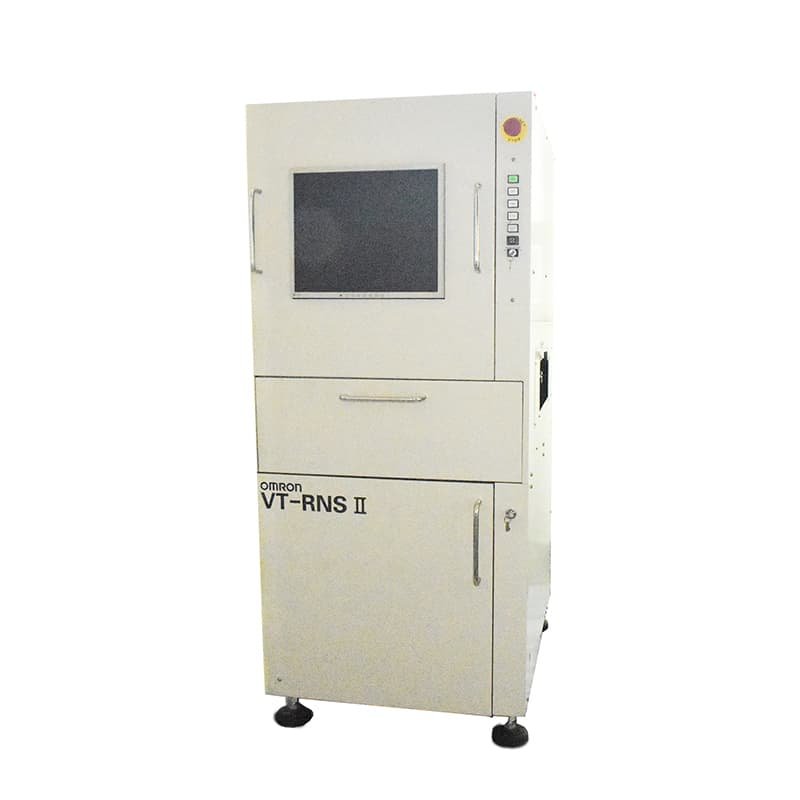
Description
Unparalleled Precision with OMRON VT-RNS II
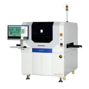
The OMRON VT-RNS II brings advanced technology to printed circuit board (PCB) inspection. As a second-generation automated optical inspection (AOI) system, this innovation is engineered for surface-mount technology (SMT) production lines, guaranteeing exceptional accuracy and reliability.
Enhanced Efficiency for High-Mix, Low-Volume Production
Designed to perform in fast-paced environments, the VT-RNS II is the perfect solution for high-mix, low-volume PCB manufacturing. Its cutting-edge capabilities efficiently identify defects, ensuring only the highest quality boards reach your customers.
Advanced Features for Seamless Integration
Building on the success of its predecessor, the VT-RNS, this model offers significant performance upgrades for in-line inspections. By incorporating advanced technology, the OMRON VT-RNS II optimizes processes to streamline production lines while maintaining impeccable quality control.
Overview
The OMRON VT-RNS II is a second-generation advanced PCB (printed circuit board) inspection system designed for automated optical inspection (AOI) on SMT (surface-mount technology) production lines. As the successor to the VT-RNS, it delivers fast and reliable in-line inspection results to prevent defective boards from reaching the customer, and is ideal for high-mix / low-volume production.
Key Features
- 20% faster post-reflow inspection – faster shutter speeds and improved image processing compared with the first-generation VT-RNS (field of view 1280 x 1024).
- EzTS (Ez-Image Teaching) – easy-to-use software for simple, automated generation and validation of inspection programs, so anyone can set up inspection programs quickly.
- Highly accurate inspection – 3-CCD color camera combined with Color Highlight Technology provides the most accurate inspection capability.
- Full-stage inspection – supports post-printing (solder paste), post-placement (before reflow) and post-reflow inspection.
- Expandable – Q-upNavi provides total support for process improvement and root-cause analysis of defects.
- World-class engineering support – Omron global sales and service network covering approx. 70 locations worldwide.
Technical Specifications
| Camera | 3-CCD color camera |
| Illumination | Ring-shaped LED (R / G / B) |
| Image resolution | 10 / 15 / 20 μm |
| Transfer method | Belt feed |
| Line height | 900 ± 15 mm |
| Rail width adjustment | Automatic |
| PCB fixing method | Outer frame |
| Power supply | AC 100 / 115 / 120 / 200 / 220 / 230 / 240 V ±10% (single phase) |
| Air pressure | 0.4 to 0.6 MPa |
| Ambient operating temperature | +10 to +35 °C |
| Ambient operating humidity | 35 to 80% RH (no condensation) |
| Dimensions (W × D × H) | M size: 700 × 900 × 1,600 mm; L size: 920 × 1,365 × 1,600 mm (excluding signal tower) |
| Weight | M size: approx. 500 kg; L size: approx. 650 kg |
Inspection Capability
| Item | M size | L size |
| PCB size (post-printing) | 50 × 50 to 333 × 255 mm | 80 × 50 to 510 × 460 mm |
| PCB size (pre / post reflow) | 50 × 50 to 333 × 255 mm | 80 × 110 to 510 × 460 mm (with PCB warpage correction unit) |
| PCB thickness | 0.3 to 2.5 mm | 0.3 to 3.0 mm |
| Clearance above PCB | 20 mm standard (40 mm optional) | 20 mm standard (40 mm optional) |
| Clearance below PCB | 40 mm | 50 mm |
| Max. inspection points | 40,000 lands / PCB; 10,000 components / PCB | 40,000 lands / PCB; 10,000 components / PCB |
Inspection Items
- Post-printing: presence of solder, insufficient / excessive solder, solder shifting, grazing, bridging, spreading, leaking.
- Post-placement (before reflow): component shifting, polarity error, missing components, wrong components, solder balls, skewing, bridging, foreign objects.
- Post-reflow: wrong components, missing components, bridging, lifting, component shifting, fillets, wettability, lead bending, adhesive, solder balls.
Data & Connectivity
- Data storage: computer hard disk; component-specific inspection data library (component types, groups, variations).
- Inspection result output: PCB name, PCB ID, component name, type of fault, etc.
- Communications: Ethernet, RS-232C. PCB feed mode: through / turnback.
- Reference position: PCB feed direction left or right; front-rail or back-rail fixing (selected at shipment).
Reviews
There are no reviews yet.